

 注: 建议图片大小150px*50px

丨
English
注: 建议图片大小150px*50px Views: 0 Author: Site Editor Publish Time: 2026-11-04 Origin: Site
Reliability in shell and tube heat exchangers hinges on one critical component: the tube sheet. A minor calculation error in this primary structural barrier risks massive equipment failure, fluid cross-contamination, and prolonged facility downtime. In this comprehensive guide, we explore the most frequent thickness miscalculations engineers and procurement teams make, and how avoiding them maximizes thermal performance and equipment lifespan.
Balance is Crucial: Too thin leads to structural deflection and leaks. Too thick causes excessive thermal stress and unnecessary material costs.
Machining Matters: Incorrect depth directly impacts drilling precision. This complicates the assembly process and causes premature wear.
Joint Integrity: The mechanical or welded connection relies heavily on the correct dimensional specification to ensure a secure, leak-proof seal.
Material Selection: Using standard pressure vessel materials requires careful calculation of corrosion allowances alongside the baseline depth.
Compliance is Non-Negotiable: Always adhere to ASME Boiler and Pressure Vessel Code and TEMA standards when determining minimum specifications.
Acting as the structural foundation of a shell and tube heat exchanger, this vital component functions as a primary pressure boundary. It separates the shell-side and tube-side fluids while providing the necessary mechanical support to keep the internal piping rigidly in its designated position. The depth of this metal plate is far from an arbitrary choice. It is a highly calculated specification that dictates the mechanical strength, thermal dynamics, and overall weight of the entire unit.
When engineers or buyers specify a gauge that deviates from exact design requirements, they inadvertently jeopardize the structural integrity of the vessel. For procurement teams and facility managers, accurately specifying these requirements is not merely a regulatory formality. Rather, it is a critical operational step to avoid premature equipment failure. Imagine a high-capacity petrochemical plant pushing flow rates to the absolute limit. A poorly specified boundary plate will inevitably yield under such stress, leading to costly, unscheduled shutdowns.
Looking at recent shifts in the thermal management sector, the push toward high-efficiency, low-carbon heat recovery systems has fundamentally altered design baselines. Plants today operate at higher pressures and handle more aggressive chemical environments than a decade ago. Consequently, relying on outdated static formulas is no longer viable. Modern engineering demands a dynamic approach to pressure boundaries. Finding the optimal thickness is no longer just about basic safety; it is about maximizing thermal transfer efficiency under extreme cycling conditions while minimizing raw material waste.
The drive to reduce raw material costs or minimize the total physical weight of a heat exchanger sometimes leads to the dangerous practice of under-sizing the primary plate. Shaving off a few millimeters might seem financially efficient on a procurement spreadsheet. However, this practice fundamentally compromises the safety of the thermal unit.
When a plate is too thin, it cannot effectively withstand the intense pressure differential between the shell and tube sides. This structural inadequacy leads to deflection. Deflection is essentially a physical bowing or bending of the solid metal under high-pressure operating conditions.
As the metal plate deflects, it physically pulls the internal piping away from its seating. This microscopic movement breaks the mechanical or welded seal at the joint, leading to immediate fluid leaks. In environments handling hazardous or reactive chemicals, this cross-contamination can trigger severe safety incidents and environmental hazards.
Beyond simple weeping at the joints, bowing introduces significant shear stress directly onto the rigid ends of the piping. Over time, as the system undergoes continuous thermal cycling, this sheer stress creates micro-cracks. These tiny fissures rapidly grow into full-scale material failures. Ultimately, this forces a total shutdown of the production line and requires emergency maintenance interventions.
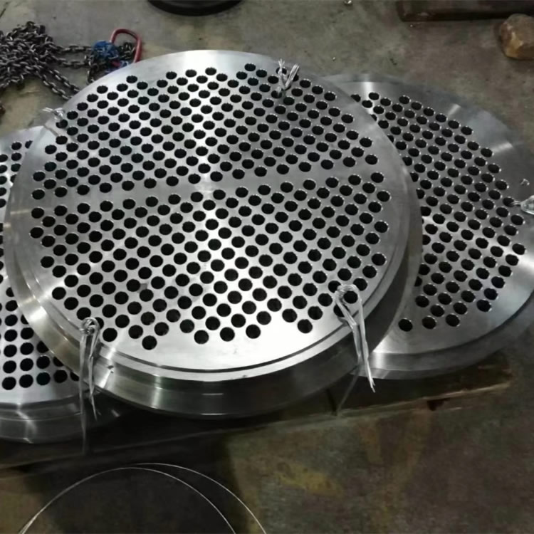
While under-sizing is a clear hazard, the opposite extreme is an equally common engineering pitfall. There is a persistent myth on the factory floor that thicker is always better. In thermal equipment, however, adding more metal can actually be detrimental to long-term performance.
Excessively thick plates hinder effective heat transfer and retain high levels of internal heat. This dynamic creates severe thermal gradients between the cooler outer surface and the blistering inner core of the metal. Such extreme temperature variations lead to significant internal stress, drastically increasing the likelihood of deep cracking or fatigue failure over time. Furthermore, purchasing heavy-duty plates—like SA516 Grade 70—beyond the necessary code specifications inflates raw material costs. It also adds unnecessary dead weight, requiring stronger, more expensive structural supports for the entire heat exchanger assembly.
Machining a perfectly straight and smooth passage becomes exponentially more difficult as the metal plate thickens. Precision on the shop floor is not merely a preference. It is a strict manufacturing requirement for long-term operational success.
The deeper the bore, the harder it is for a machinist to keep the CNC drill bit perfectly aligned. If the operator fails to maintain the correct drilling tolerance, the drill can wander or experience runout. When these bores are not perfectly straight, inserting the internal piping becomes an arduous, forceful task. If the final fit is compromised due to poor machining, the piping may vibrate violently during normal fluid flow. This flow-induced vibration causes fretting at the entry point, leading to rapid thinning of the metal wall and inevitable, catastrophic leaks.
The integrity of the connection between the piping and the main plate dictates the overall lifespan of the exchanger. When the dimensional depth is mismatched, standard assembly techniques are rendered ineffective. This applies to both roller expansion and seal welding.
Specifically, if the plate is too thin, there is simply insufficient internal surface area for the pipe to grip during the mechanical expansion process. This lack of friction results in a weak mechanical bond that will loosen under pressure. Conversely, an overly thick plate makes full-depth expansion mechanically difficult for assembly crews. If the expansion tool cannot reach the full depth, it leaves an unexpanded crevice behind. These stagnant, microscopic gaps become prime targets for crevice corrosion, where trapped acidic fluids slowly eat away at the tube-to-tubesheet joint.
In addition, extreme thickness differences create massive welding challenges. When a thin pipe wall meets a massive, thick plate, the plate acts as a giant heat sink. This thermal imbalance makes it incredibly difficult for welders to achieve proper penetration. Consequently, this leads to an increased risk of burn-through on the thin pipe or cold, brittle welds that crack under operational stress.
Mechanical strength calculations correctly identify the absolute minimum metal required to hold back pressure on the day of commissioning. However, these static calculations often overlook the inevitable reality of long-term environmental degradation.
Using standard pressure vessel carbon steels provides excellent initial strength and weldability, but these materials are rarely immune to chemical attack. The critical mistake lies in neglecting to add a corrosion allowance—typically a sixteenth or an eighth of an inch—to the final depth calculation. Without this sacrificial buffer, the component will reach its critical minimum thickness long before the end of the facility expected service life. This oversight eventually forces an expensive, premature replacement that could have been avoided with a fraction of an inch of extra steel.
To clearly illustrate the commercial and operational impacts of sizing errors, review the performance matrix below. This engineering breakdown highlights why striking the perfect dimensional balance is vital for your equipment.
Design Condition | Mechanical Integrity | Thermal Dynamics | Commercial Impact |
|---|---|---|---|
Under-Sized | High risk of deflection, joint seal breakage, and shear stress on piping. | Adequate heat transfer, but structural shifting disrupts fluid flow paths. | Low initial cost, but guarantees expensive emergency shutdowns and replacements. |
Optimally Sized | Maintains rigid pressure boundary; supports perfect CNC drilling tolerances. | Balanced thermal gradients prevent internal stress cracking. | Maximizes ROI through decades of uninterrupted, leak-free service. |
Over-Sized | Creates deep crevices during expansion; high risk of cold welds. | Acts as a heat sink, trapping heat and causing severe thermal fatigue. | Wastes budget on surplus raw material and requires heavier structural supports. |
Determining the optimal gauge for a critical pressure boundary should never be based on intuition. It must follow strict, verified engineering protocols. Instead of viewing thickness as an abstract calculation, procurement teams should evaluate suppliers based on concrete manufacturing capabilities. Here is what a professional selection standard looks like in practice:
Material Grade Verification: Ensure the manufacturer works with certified materials. Whether you require customized stainless steel like 304 or 316L for corrosive environments, or robust carbon steel plates like SA516 Gr.70 for high-pressure vessels, the material must match the exact design pressure rating.
CNC Machining Precision: The supplier must guarantee micro-level precision. Every tube hole must be drilled with strict tolerances to prevent runout, ensuring the internal piping fits perfectly without forced scoring.
Digital Validation: Top-tier manufacturers utilize 3D Finite Element Analysis software. By simulating dynamic thermal cycling digitally, engineers can optimize the exact thickness required to satisfy rigorous safety codes while maintaining maximum thermal efficiency.
Code Compliance: The final product must strictly adhere to ASME Section VIII guidelines for pressure containment and TEMA standards for geometric layout.
Even with a flawless design and premium materials, maintenance teams must remain vigilant. Proactive maintenance and rigorous inspection protocols are essential to identify early signs of degradation. Routine visual inspections are the first line of defense. Technicians should actively look for structural bowing or subtle moisture weeping at the joints during hydrostatic testing.
Because visual checks cannot detect internal micro-cracking, Non-Destructive Testing methods are mandatory. Ultrasonic Testing measures the remaining metal thickness accurately. Meanwhile, Eddy Current Testing assesses the immediate joint area for pitting. When damage is detected, facility managers face a critical choice. Minor issues, like localized weeping, can often be repaired by re-rolling the affected pipes. However, if the main plate shows signs of permanent deflection due to original under-sizing, partial repairs are inherently unsafe. In such scenarios, replacing the entire assembly with a unit designed to current, verified calculations is the only viable path forward.
Specifying the correct dimensions for a heat exchanger structural foundation is a delicate balance of mechanical engineering, material science, and precision machining. Mistakes regarding the depth, drilling precision, or joint expansion can compromise the safety and efficiency of the entire cooling system.
By strictly adhering to ASME and TEMA standards, incorporating appropriate corrosion allowances, and avoiding the temptations of under-sizing or over-engineering, you ensure a safe, long-lasting thermal unit. Protecting your investment starts with demanding precision from the very first calculation. If your facility requires expertly engineered, highly precise components tailored to your exact operational parameters, partner with experienced manufacturers. Explore the customized stainless steel and carbon steel solutions available at Graceland to secure a leak-proof, high-performance future for your thermal equipment.
The minimum thickness cannot be generalized. It is strictly dictated by TEMA and ASME engineering standards. Engineers calculate this exact value by evaluating the design pressure, the outside diameter of the internal piping, the spacing layout, and the allowable stress of the chosen metal. However, as a general manufacturing rule of thumb, the baseline depth should never be less than the outside diameter of the pipes it supports to ensure sufficient structural rigidity.
SA516, specifically Grades 60 and 70, is a premium-quality carbon steel plate engineered primarily for moderate to lower temperature service in pressure vessels. It is exceptionally popular because it offers a superior combination of high mechanical strength, excellent notch toughness, and outstanding weldability. This makes it highly reliable for enduring decades of continuous industrial use.
The depth directly dictates the available internal contact area for the joint. Adequate depth provides a robust surface for the pipe to grip during the roller expansion process, ensuring a strong mechanical hold. Conversely, if the plate is excessively thick, achieving a full-depth expansion becomes difficult, leaving unexpanded crevices that are highly prone to aggressive chemical corrosion.
Drilling tolerance refers to the strictly defined acceptable limits of deviation regarding the diameter, straightness, and precise spacing of a machined bore. Maintaining strict tolerances is absolutely critical. If a bore is too large, the joint will leak. If it is too tight, forcing the pipe into place will cause severe mechanical scoring and residual stress before the equipment even operates.
In the vast majority of cases, a permanently warped or deflected plate cannot be safely repaired. While minor joint leaks can sometimes be temporarily addressed by re-expanding or seal welding, structural deflection indicates that the solid metal has yielded under operational pressure. Once the fundamental geometry is compromised, it loses its mechanical integrity and generally requires complete replacement to maintain safety compliance.
Engineers utilize specific formulas outlined in the ASME Boiler and Pressure Vessel Code Section VIII. The calculation factors in the maximum allowable working pressure, the maximum operating temperature, the specific yield strength of the chosen material, and the tube pitch geometry. Modern engineering teams also run these static calculations through Finite Element Analysis software to simulate real-world thermal stress and ensure the plate will not deform under dynamic loads.
According to TEMA standards, the machining tolerance for these bores is exceptionally tight, often requiring precision within a few thousandths of an inch depending on the pipe diameter. The inner surface finish must also be perfectly smooth, free from burrs or longitudinal scoring, to ensure a flawless metal-to-metal seal during the expansion or welding process.


