

 注: 建议图片大小150px*50px
丨
English
注: 建议图片大小150px*50px Views: 0 Author: Site Editor Publish Time: 2026-07-14 Origin: Site
Industrial heat exchange involves massive operational stakes. Specifying incorrect components causes severe ripple effects across your facility. A poor choice goes beyond merely reducing thermal efficiency. It actively accelerates equipment fouling. It heavily increases maintenance burdens. It ultimately triggers premature equipment failure. Engineers naturally aim to maximize surface area to optimize heat transfer. However, mechanical realities heavily restrict these theoretical goals. You must carefully balance thermal optimization against aggressive thermal cycling. You must account for highly corrosive environments. You must withstand constant structural vibration.
Selecting the right industrial finned tube demands a rigorous evaluation approach. You must scrutinize specific operating parameters. You must rigorously verify material compatibility. You must also hold suppliers to strict manufacturing standards. Relying solely on baseline procurement metrics will invite systemic failure. We will guide you through matching precise environments with correct attachment methods, ideal materials, and proven quality frameworks.
Operating temperature and the presence of corrosive media dictate the fin attachment method (e.g., embedded vs. L-foot).
Galvanic corrosion and thermal fatigue are the primary failure risks when base tube and fin materials are mismatched.
Quality verification (material traceability, bond resistance testing) is non-negotiable for high-pressure or high-temperature applications.
Before selecting any hardware, you must establish strict operational boundaries. You cannot specify a reliable Fin Tube without knowing its exact working conditions. Every heat exchanger faces unique environmental challenges. We outline four critical evaluation areas below.
Temperature Thresholds: You must define your maximum operating temperature limits. Base tubes and fins often consist of dissimilar metals. These metals expand at different rates when heated. For example, aluminum expands much faster than carbon steel. This difference causes severe bond degradation over time. The mechanical connection loosens. When the fin separates from the tube, thermal resistance spikes. The unit rapidly loses cooling capacity.
Atmospheric & Fluid Corrosivity: You must assess chemical exposure thoroughly. Offshore platforms introduce high ambient salinity. Exhaust systems often contain acidic sulfur compounds. Corrosive environments demand specific physical protection strategies. An exposed base tube will suffer accelerated pitting. We recommend evaluating both the internal tube fluid and the external atmospheric gases.
Mechanical Stress & Vibration: Fluids moving across tubes generate massive external forces. High fluid velocities create heavy pressure drops. They also induce significant turbulence. This turbulence triggers severe continuous vibration. You must account for these forces during specification. High-vibration zones require maximum fin rigidity. Weak fins will bend, deform, or snap under continuous cyclic loading.
Fouling Factors: Evaluate the particulate load present in your air or fluid streams. High-fouling environments severely restrict performance. Dust, ash, or chemical scales build up between the fins over time. This buildup chokes airflow. It traps heat against the core. You must select specific fin pitches to combat this issue. Heavy fouling dictates wider fin spacing. You must also choose appropriate profiles. Solid profiles allow for effective high-pressure cleaning.
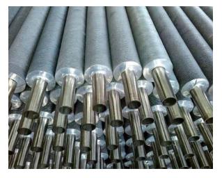
Matching the attachment method to your environment ensures long-term reliability. A mismatched connection will degrade rapidly under stress. We compare the four primary configurations below.
Mechanism: Manufacturers extrude fins from a solid outer metal sleeve directly onto an inner base tube. This process uses high rotary compression. The outer sleeve forms a continuous, seamless fin structure over the core.
Outcomes: This design delivers maximum corrosion protection. The base tube remains completely shielded from atmospheric elements. The continuous extrusion withstands aggressive high-pressure washing easily. You will find this design ideal for extreme offshore facilities. It excels in highly corrosive atmospheric conditions.
Mechanism: A specialized machine plows a continuous helical groove into the base tube surface. The machine mechanically embeds the fin strip into this groove. Rollers then press the displaced metal tightly against the fin base.
Outcomes: This mechanical lock supports extremely high temperatures. The bond remains secure up to roughly 400°C. It survives extreme thermal cycling without losing its fin-to-tube connection. We recommend this configuration for high-heat applications demanding strict mechanical reliability.
Mechanism: Machines form a flat metal strip into an "L" shape. They wrap this strip around the tube under high tension. The "L" base rests flat against the tube surface. LL and KL variations offer overlapping feet or knurled tube surfaces for enhanced grip.
Outcomes: These configurations provide highly cost-effective solutions. They suit lower-temperature operations well. Standard L-foot fins handle temperatures up to 150°C. LL or KL designs stretch this limit to roughly 250°C. They serve standard air-cooled heat exchangers perfectly. You should use them where thermal cycling remains moderate.
Mechanism: A continuous high-frequency electrical current welds the fin strip directly to the base tube. This fuses the two metals together completely.
Outcomes: This process provides a permanent metallurgical bond. The bond cannot loosen through thermal expansion. You must choose between serrated and solid variations. Serrated designs cut the fin into segments. This creates higher heat transfer coefficients in clean environments. Solid designs remain mandatory for heavy-fouling environments. Boilers and economizers require solid fins to prevent severe ash impaction.
Technology | Attachment Method | Max Temp Limit | Primary Advantage | Best Application |
|---|---|---|---|---|
Extruded (Bi-Metallic) | Rotary Compression | ~300°C | Complete base tube protection | Offshore, High-salinity |
Embedded (G-Fin) | Mechanical Grooving | ~400°C | Extreme thermal cycling resilience | High-heat industrial plants |
L-Foot / LL / KL | Tension Wrapping | 150°C - 250°C | Cost-effective manufacturing | Standard air coolers |
High-Frequency Welded | Metallurgical Fusion | Base Metal Limit | Permanent structural bond | Boilers, Heavy-duty heaters |
Materials define the ultimate performance boundaries of your equipment. You must weigh thermal conductivity against chemical resilience carefully.
Thermal Conductivity vs. Durability: Engineers frequently choose aluminum for fins. Aluminum offers exceptionally high thermal conductivity. It also keeps component weight very low. However, aluminum lacks extreme structural durability. It degrades rapidly in highly acidic conditions. Copper offers excellent conductivity and better corrosion resistance in certain water applications. Stainless steel provides unmatched chemical resistance. It survives extreme industrial exhausts easily. However, stainless steel yields lower thermal conductivity. You must increase the surface area to match aluminum's cooling power. You must balance these engineering trade-offs carefully.
The Galvanic Corrosion Threat: Pairing dissimilar metals creates hidden physical dangers. Wet environments transform these metals into a literal battery. If you pair aluminum fins and bare copper tubes in damp conditions, a severe galvanic reaction begins. The aluminum acts as an anode. It corrodes rapidly to protect the copper. You must mitigate this galvanic threat aggressively. You can apply specialized protective coatings. Alternatively, you can utilize extruded designs. Extruded outer sleeves completely encapsulate the inner tube. This physical barrier stops electrolytic bridging entirely.
Weight Considerations: The chosen metals directly impact total structural mass. A stainless steel fin assembly weighs significantly more than an aluminum equivalent. This added mass strains the surrounding heat exchanger framework. You must verify structural load capacities before upgrading materials. Heavier units require heavily reinforced pipe racks. They also demand stronger concrete foundation supports. Failing to account for weight invites severe structural fatigue over time.
Assumed quality often causes catastrophic system failures. You must demand verifiable proof of manufacturing excellence from your suppliers.
Bond Integrity: Do not accept vague marketing claims regarding thermal contact resistance. You must evaluate the physical bond strength directly. A weak bond creates an insulating air gap between the fin and the tube. This gap severely destroys cooling capacity. Look for manufacturers providing verifiable pull-tests. These tests measure the exact force required to rip the fin from the base metal. You should also request metallurgical cross-sections. These microscopic images prove the complete absence of micro-voids in welded joints.
Industry Certifications: Premium manufacturers maintain strict compliance documentation at all times. You must look for specific recognized industry standards. ASME Section VIII dictates rigid pressure vessel rules. API 661 specifically governs air-cooled heat exchangers for critical refinery services. ISO standards ensure consistent factory quality management protocols. The absence of these certifications signals extreme operational risk. You should automatically disqualify uncertified vendors from your procurement list.
Material Traceability: Counterfeit alloys regularly flood global supply chains today. A substandard steel tube will rupture violently under high pressure. You must demand certified Mill Test Reports (MTRs) for all metal components. An MTR verifies the exact chemical composition of your metal. It proves the alloy meets promised metallurgical specifications. It tracks the material from the original foundry directly to your facility. Strict traceability prevents catastrophic equipment failures. It ensures your entire system survives its intended operational lifespan safely.
Procuring a reliable industrial finned tube assembly requires systematic evaluation. Use this specific checklist to screen potential manufacturing partners effectively.
Custom Tooling Availability: Do they offer custom tooling for specific fin pitches and heights? Standard sizes rarely optimize complex fluid cooling tasks perfectly.
Testing Capabilities: What are their non-destructive testing (NDT) capabilities? They must offer eddy current testing or dye penetrant inspections to find hidden metal flaws.
Industry Evidence: Can they provide detailed case studies? You need actual proof demonstrating extended lifespans in your specific industry sector.
Independent Quality Assurance: Do they maintain an active quality assurance program completely independent of their fast-paced production teams?
Schedule Management: Are they truly capable of managing tight delivery schedules without bypassing critical quality control checkpoints?
Next Steps: We strongly encourage engineers and buyers to abandon guesswork. Bring your precise thermal data directly to a specialized manufacturer. Share your exact internal fluid specifications. Provide your rigid external dimensional constraints. A qualified manufacturing partner will run a customized heat transfer calculation. They will mathematically prove the optimal geometric design for your facility.
The right fin configuration bridges a massive engineering gap. It perfectly connects theoretical heat transfer models to practical longevity. Harsh environments destroy inadequate components quickly. You must evaluate thermal cycling limits, corrosive threats, and precise mechanical stresses before finalizing any procurement decisions.
Avoid the costly trap of over-specifying. Demanding exotic alloys for standard applications wastes critical capital rapidly. Conversely, strictly avoid under-specifying. Using standard L-foot designs in extreme thermal cycling applications risks rapid systemic failure. Your components must match your environmental reality perfectly.
You must act to secure reliable operations. Prompt your engineering team to compile exact operational data today. Consult specialized manufacturers immediately. Request a detailed technical data sheet and a customized quote based entirely on your specific application parameters.
A: Serrated designs feature small vertical cuts along the fin strip. These cuts disrupt airflow and create turbulence. This turbulence significantly increases heat transfer efficiency. However, serrated cuts trap dust and ash easily. Solid designs use a continuous metal strip. They transfer heat slightly less efficiently. However, solid fins provide excellent fouling resistance. You can clean them easily using high-pressure washers.
A: Thermal cycling involves continuous rapid heating and cooling. Base tubes and fins often expand at different rates. This differential expansion heavily stresses the mechanical bond. Over time, tension-wrapped designs loosen. The fin pulls away from the tube surface. This physical separation creates an insulating gap. This gap severely reduces your heat transfer efficiency.
A: Standard aluminum L-foot designs operate safely up to approximately 150°C (300°F). Above this threshold, the aluminum begins to expand much faster than the underlying steel tube. The tension wrapping loses its mechanical grip. If your application exceeds this baseline limit, you must upgrade. You should select embedded or extruded designs.
A: Embedded G-fins offer exceptional cost efficiency for high-temperature applications. They maintain a secure mechanical lock up to 400°C. Extruded designs provide excellent atmospheric corrosion protection but cost significantly more to manufacture. If your operating environment involves high heat but lacks severe external corrosive elements, an embedded design delivers optimal reliability.


