

 注: 建议图片大小150px*50px
丨
English
注: 建议图片大小150px*50px Views: 0 Author: Site Editor Publish Time: 2026-08-28 Origin: Site
Heat transfer surface area dictates the operational lifespan of any industrial heat exchanger. Specifying the exact geometry and material of a finned surface is a strict engineering decision. Mismatching these parameters with the operating environment leads to severe consequences. You risk rapid fouling, galvanic corrosion, thermal degradation, and unplanned downtime. Specification errors cost facilities heavily in lost production and frequent maintenance. We evaluate different fin types, material combinations, and mechanical bonds against specific thermal, chemical, and environmental realities. By matching the component to the exact operating conditions, engineers ensure optimal performance and long-term operational efficiency. You must evaluate the physical realities of your gas stream before finalizing any design. We will break down the exact mechanical limits of applied and welded fins. You will learn how to match base tubes with fin materials to prevent galvanic failure.
Temperature Dictates Bond Type: Mechanical bonds (like L-foot) are restricted to moderate temperatures, while welded or embedded (G-type) fins are mandatory for high-temperature, high-stress environments.
Fouling Realities Override Theoretical Efficiency: High Fins Per Inch (FPI) maximizes theoretical heat transfer but will rapidly fail or require excessive maintenance in particulate-heavy or "dirty" gas streams.
Material Synergy is Critical: The base tube and fin material must be evaluated not just for thermal conductivity, but for differing thermal expansion coefficients and galvanic corrosion risks.
Geometry Impacts Maintenance: Serrated fins offer higher turbulence and heat transfer for clean gases, while solid fins are easier to clean and more durable in abrasive environments.
Selecting the correct heat transfer component requires balancing conflicting engineering priorities. You must weigh thermal performance against mechanical durability. Maximizing surface area typically involves specifying thinner, denser fins. These thin profiles transfer heat rapidly. However, they lack structural integrity under high-velocity or abrasive flows. Ash, sand, or particulate matter in the gas stream will erode thin fins quickly. Conversely, thicker fins resist abrasion but reduce the overall heat transfer surface area. Engineers must calculate the exact velocity and particulate load to find the optimal fin thickness. We see failures constantly when designers prioritize theoretical heat transfer over physical durability. A paper design means nothing if the fins erode within six months of startup.
Evaluating an Industrial Finned Tube solely on upfront material cost is a flawed strategy. Initial capital expenditure represents only a fraction of the actual financial impact. Success depends on long-term operational efficiency. You must frame your evaluation around maintenance intervals and cleaning costs. Consider the replacement frequency and the ability to customize the tube for specific lifecycle requirements. A cheaper mechanical bond might save money initially but will fail prematurely under thermal cycling. This failure necessitates a complete bundle replacement. You pay for the crane, the scaffolding, the downtime, and the replacement bundle. The initial savings evaporate instantly.
Defining the exact operating conditions prior to selection is mandatory. Environmental profiling prevents catastrophic failures in harsh conditions. You must document several critical parameters before consulting a manufacturer. These parameters dictate the baseline requirements for materials and bonding methods.
Calculate the internal fluid corrosivity and maximum operating pressure.
Measure the external gas stream particulate load and abrasive qualities.
Determine the maximum continuous operating temperature and peak excursion limits.
Record the thermal cycling frequency and temperature differential.
Identify exposure to harsh elements like marine salinity or high-sulfur flue gas.
Manufacturers create L-foot fins using a tension-wrapped process. They form the aluminum fin strip into an 'L' shape at the base. This broad base maximizes surface contact with the core tube. The continuous L-shaped base also provides a layer of atmospheric corrosion protection for the underlying metal. LL-foot fins use an overlapping base design. This overlap completely encloses the base tube for enhanced protection. The overlapping feet prevent moisture from reaching the carbon steel underneath.
These applied fins operate best in clean air-side service. They handle moderate temperatures effectively. Industry standards typically restrict their use to environments between 130°C and 150°C. They are common in standard air-cooled heat exchangers where thermal stress remains low. You will find them in basic cooling applications where the ambient air carries minimal dust or corrosive elements.
The primary limitation is fin relaxation. Thermal cycling causes the aluminum fin and the steel base tube to expand at different rates. Aluminum expands roughly twice as fast as carbon steel. Over time, this differential expansion breaks the mechanical tension. The fin loses tight thermal contact with the tube. A microscopic air gap forms between the fin foot and the tube wall. Air is a terrible conductor of heat. Heat transfer efficiency drops dramatically once this contact is compromised.
The KL-foot manufacturing process involves knurling the base tube before applying the fin. The machine cuts a cross-hatched pattern into the outer wall of the base tube. The L-shaped fin base is then wrapped under tension into the knurled surface. The aluminum deforms slightly into the knurling. This creates a significantly stronger mechanical grip. It resists vibration much better than a standard L-foot.
Extruded fins utilize a bimetallic cold rotary extrusion process. An outer aluminum tube is compressed onto an inner base tube. The fins are extruded directly from the outer aluminum layer using massive pressure. This creates a seamless, integral fin structure. There is no joint between the fin and the outer sleeve.
These designs offer superior mechanical bonding. The extruded design provides exceptional corrosion protection because the base tube is entirely encased in aluminum. They suit moderate-to-high temperatures. They perform exceptionally well in wet or corrosive external environments where moisture would otherwise attack the base tube. Offshore platforms frequently use extruded fins to combat salt spray.
Manufacturing costs for extruded and KL-foot designs are higher than standard L-foot options. The cold extrusion process requires specialized tooling and significant energy. The heavy aluminum outer tube also adds considerable weight to the final heat exchanger bundle. You must account for this extra weight when designing the structural supports.
G-type fins rely on a mechanically locked bond. The manufacturing process plows a shallow spiral groove into the outer wall of the base tube. The fin strip is inserted directly into this groove. Rollers then peen the displaced metal back against the base of the fin. This locks the fin securely in place. The fin becomes physically embedded into the tube wall.
This embedded design is the industry standard for high thermal cycling. It handles high-temperature applications effectively. G-type fins operate reliably at continuous temperatures up to 400°C. The locked groove prevents the fin from relaxing or separating from the tube during rapid heating and cooling phases. When the aluminum expands, it pushes harder against the peened groove, maintaining thermal contact.
The grooving process does remove a small amount of metal from the base tube. This slight reduction in wall thickness must be factored into pressure calculations. You cannot use thin-walled tubes for G-type fins. The manufacturing process also demands precise tolerances. If the groove is too deep, it compromises tube integrity. If it is too shallow, the fin will pull out during operation.
High-frequency welding creates a permanent metallurgical bond. An electrical current heats the base of the fin and the outer surface of the tube to the forging temperature. Pressure rollers then forge the two metals together. This continuous welding process eliminates all contact resistance. The fin and tube become a single, unified structure. Heat flows seamlessly from the tube wall into the fin.
This is the ultimate solution for extreme heat and heavy industrial applications. You will find them in utility boilers, heat recovery steam generators, and fired heaters. Standard configurations operate continuously at fin temperatures up to 400°C. OEM customization with specialized alloys allows them to exceed this limit for much higher-temperature gas streams. We regularly specify welded stainless steel fins for exhaust gas temperatures exceeding 600°C.
Improper material selection can lead to weld-root corrosion. The heat-affected zone at the weld joint is vulnerable if the alloys are incompatible. Furthermore, the rigid metallurgical bond struggles under extreme differential expansion. If the fin and tube expand at vastly different rates, the thermal stress can shear the weld. You must match the thermal expansion coefficients of the fin and tube materials closely.
Mechanical Bond and Temperature Limit Comparison
Bond Type | Manufacturing Method | Maximum Operating Temperature | Primary Industrial Application |
|---|---|---|---|
L-Foot / LL-Foot | Tension-wrapped base | 130°C - 150°C | Clean air cooling, low thermal stress |
KL-Foot | Knurled tube, tension wrap | 250°C - 260°C | Moderate temp, vibration resistance |
Extruded | Cold rotary extrusion | 285°C - 300°C | Corrosive external environments |
G-Type (Embedded) | Plowed groove, peened lock | 400°C | High thermal cycling, high temp |
High-Frequency Welded | Metallurgical forge weld | 400°C+ (Alloy dependent) | Boilers, fired heaters, extreme duty |
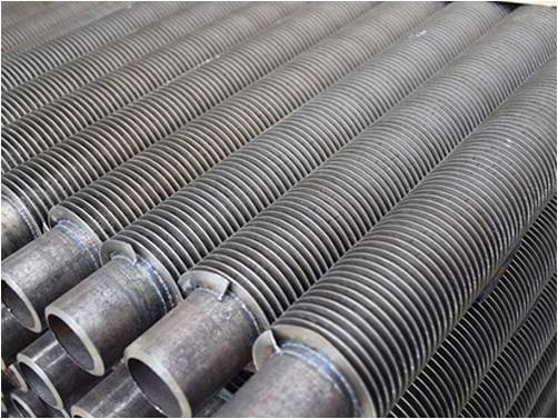
Engineers rarely use the same material for both the tube and the fin. Heat exchangers require bimetallic combinations to balance conflicting needs. The base tube must withstand internal fluid pressure and resist internal corrosion. The fin must provide maximum thermal conductivity to transfer heat to the surrounding gas. You must select materials that satisfy both requirements simultaneously. A carbon steel tube handles high-pressure steam, while an aluminum fin dissipates the heat efficiently.
Galvanic corrosion is a severe risk in bimetallic designs. When two dissimilar metals contact each other in the presence of an electrolyte, a galvanic cell forms. Moisture from humidity or rain acts as this electrolyte. For example, pairing copper tubes with aluminum fins in a marine environment accelerates aluminum degradation. The aluminum acts as an anode and sacrifices itself to protect the copper. You must consult galvanic series charts to avoid combinations that self-destruct in wet conditions.
Thermal expansion mismatch presents another significant engineering challenge. Metals expand at different rates when heated. Aluminum expands much faster than carbon steel. If you pair an aluminum fin with a steel tube in a high-temperature environment, the fin will push away from the tube. This breaks the mechanical bond and destroys thermal efficiency. You must pair materials with compatible coefficients of thermal expansion for high-heat applications.
Material Compatibility and Application Guide
Base Tube Material | Fin Material | Common Application | Primary Risk Factor |
|---|---|---|---|
Carbon Steel | Aluminum | Standard air coolers, moderate temp | Galvanic corrosion in wet environments |
Stainless Steel | Aluminum | Corrosive internal fluids, moderate temp | Thermal expansion mismatch at high heat |
Carbon Steel | Carbon Steel | High temp boilers, heavy fouling | External atmospheric corrosion |
Stainless Steel | Stainless Steel | Extreme corrosive gas streams | Lower overall thermal conductivity |
Copper | Aluminum | HVAC, commercial refrigeration | Severe galvanic corrosion if exposed to salt |
Ferrous metals dominate heavy industry. Carbon steel and stainless steel are the standard choices for high-pressure environments. They handle highly corrosive internal fluids safely. You will specify these materials for petrochemical processing, oil refining, and power generation. They maintain their structural integrity at extreme temperatures. When a plant processes sour gas or high-pressure steam, steel is the only viable option for the pressure boundary.
These metals involve a specific trade-off. They offer excellent mechanical strength and superior corrosion resistance. However, their thermal conductivity is relatively low compared to non-ferrous metals. A steel fin transfers heat much slower than an aluminum fin. To compensate for this lower conductivity, engineers often increase the overall surface area or specify a welded bond to eliminate contact resistance. We frequently use high-frequency welding for all-steel assemblies to maximize heat flow.
Non-ferrous metals excel at moving heat. Copper and aluminum alloys offer maximum thermal conductivity. They are the standard materials for HVAC systems, commercial refrigeration, and lower-temperature industrial cooling. Aluminum is particularly favored for its high conductivity-to-weight ratio. It keeps heat exchanger bundles light and efficient. This reduces the structural steel requirements for the supporting framework.
These materials have strict structural limitations. They lack the tensile strength of steel. They are highly susceptible to erosion at high gas velocities. Particulate matter in the air stream will quickly wear down aluminum fins. Furthermore, they have strict temperature ceilings. Aluminum loses its mechanical strength rapidly as temperatures approach 300°C. You cannot use aluminum fins in direct fired heater exhausts.
Specifying a high Fins Per Inch (FPI) count is a common engineering trap. On paper, 15+ fins per inch maximizes theoretical heat transfer. It provides massive surface area in a compact footprint. However, this is a critical error in dirty, dusty, or ash-laden environments. High FPI tightens the gap between each fin. Particulate matter bridges this narrow gap instantly. The heat exchanger clogs, pressure drop spikes, and thermal performance plummets.
You must establish strict clearance requirements based on the gas stream. Lower the FPI and increase fin spacing for dirty environments. Wider spacing allows particulate matter to pass through the bundle without lodging between the fins. This increased clearance is mandatory for effective maintenance. It allows operators to utilize soot blowing or high-pressure washing to clean the tubes during scheduled downtime. If the fins are too tight, the water jet cannot penetrate the bundle, and the dirt remains trapped.
Fins Per Inch (FPI) Selection Guidelines
Gas Stream Condition | Recommended FPI | Maintenance Approach |
|---|---|---|
Clean Air (HVAC, standard cooling) | 10 - 14 FPI | Light air blowing, minimal washing |
Moderate Dust (Industrial ambient) | 7 - 9 FPI | Routine pressure washing |
Heavy Particulate (Coal ash, exhaust) | 3 - 6 FPI | Aggressive soot blowing, hydro-blasting |
Severe Fouling (Sticky residue, heavy tar) | Bare Tube or 1-2 FPI | Mechanical scraping, chemical baths |
Serrated fins feature vertical cuts along the fin strip. These segments increase gas turbulence as air flows over the tube. This turbulence breaks up the thermal boundary layer. It significantly improves heat transfer coefficients. Serrated designs are highly effective in clean, high-temperature gas streams where fouling is not a concern. The segmented design also reduces the physical weight of the tube slightly.
Solid fins remain continuous without any cuts or segments. They are mandatory for environments with heavy fouling. Serrations act as traps for debris, ash, and fibers. Once a serrated fin clogs, it is exceptionally difficult to clean mechanically. Solid fins provide a smooth surface that resists buildup. They are significantly easier to clean using standard industrial methods. You can highly customize a solid Fin Tube based on specific temperature limits, corrosion resistance needs, and budget constraints. When we design for refineries, we almost exclusively specify solid fins to ensure the maintenance crews can actually clean the bundles during turnarounds.
Procurement teams must enforce strict inspection metrics. You cannot verify bond integrity visually. For embedded G-type fins, require documented pull tests to measure the mechanical lock strength. The manufacturer must prove the fin will not pull out under operational stress. For high-frequency welded tubes, mandate metallographic examinations. These destructive tests verify the depth and quality of the metallurgical bond. The lab cuts the tube, polishes the cross-section, and examines the weld under a microscope.
Contact resistance testing is also crucial to ensure thermal efficiency. Mitigate procurement risks by demanding comprehensive documentation. Require Material Test Reports (MTRs) for all metal heats used in production. Request documented quality control procedures from the supplier before issuing a purchase order. A reputable manufacturer will provide full transparency regarding their testing protocols and failure rates. Never accept components without verifiable test data.
Industrial heat exchangers operate under immense pressure and thermal stress. Mandate that the chosen component meets all relevant regulatory frameworks. Common standards include the ASME Boiler and Pressure Vessel Code and API 661 for air-cooled heat exchangers. Compliance ensures the component can withstand the specified operating parameters safely. Inspectors will reject non-compliant bundles during site commissioning.
Emphasize the importance of full material traceability. Counterfeit or sub-spec alloys cause catastrophic failures in industrial settings. If a manufacturer substitutes a lower-grade steel, the tube may rupture under pressure or corrode prematurely. Traceability guarantees that the chemical composition and mechanical properties of the metal match the engineering specifications exactly. You must track every tube back to the original steel mill.
Compile exact thermal data, chemical exposure levels, and particulate loads before selecting any fin geometry or material.
Specify applied fins for low-temperature, clean environments to optimize budget and efficiency.
Mandate G-type embedded or high-frequency welded fins for high-temperature applications or systems with frequent thermal cycling.
Reduce your Fins Per Inch specification strictly based on the environmental dirtiness to prevent rapid fouling.
Consult with a specialized OEM manufacturer to conduct custom thermal modeling and prototype testing for your specific gas stream.
A: The maximum operating temperature is limited by the melting point and structural integrity of the aluminum fin material. Extruded fins typically have a strict temperature ceiling. Industry standards limit their continuous use to approximately 285°C to 300°C. Exceeding this temperature causes the aluminum to lose mechanical strength and degrade rapidly.
A: High fin density traps debris. A high count, such as 15 FPI, creates narrow gaps that bridge quickly with ash or dust. This leads to rapid fouling. The particulate buildup blocks airflow, causing an increased pressure drop and severely degraded thermal performance. Dirty environments require lower FPI for clearance.
A: The G-type uses an embedded, mechanically locked groove plowed into the base tube. This locked bond withstands high temperatures and thermal cycling up to 400°C. The L-foot relies on surface-wrapped tension. It simply hugs the outside of the tube. L-foot fins are restricted to lower temperatures to prevent relaxation.
A: Specify serrated fins exclusively for clean, high-temperature gas streams. The cut segments create maximum turbulence. This breaks boundary layers and increases heat transfer efficiency. However, you must avoid them in dirty environments. Serrations trap debris and are nearly impossible to clean mechanically without damaging the fins.
A: Prevent galvanic corrosion by selecting compatible alloys that sit close together on the galvanic series chart. In wet environments, use extruded fins. The extrusion process completely covers the base tube in a seamless aluminum layer. This physical barrier prevents moisture from acting as an electrolyte between dissimilar metals.
A: Yes, they perform exceptionally well in corrosive environments. However, both the base tube and the fin material must be specified with highly corrosion-resistant alloys. You must use materials like stainless steel, duplex steel, or high-nickel alloys. The weld filler and process must also match these corrosion-resistant specifications exactly.


