

 注: 建议图片大小150px*50px
丨
English
注: 建议图片大小150px*50px Views: 0 Author: Site Editor Publish Time: 2026-08-20 Origin: Site
Specifying industrial thermal management systems requires matching fluid dynamics, spatial constraints, and operational boundaries to the correct mechanical design. Miscalculating thermal requirements or material compatibility leads to process bottlenecks, excessive energy consumption, and premature equipment failure. Relying on legacy specifications often results in over-engineering or severe under-performance in modern processing environments.
Engineers and plant managers face the complex task of aligning fluid properties, physical footprint limitations, and maintenance capabilities with specific thermal technologies. This guide provides a vendor-neutral, engineering-focused framework for evaluating and selecting the optimal unit based on empirical process data and long-term reliability. By systematically analyzing process requirements and equipment capabilities, you can specify a solution that ensures continuous, efficient operation without unnecessary downtime.
Fluid characteristics dictate the baseline: Viscosity, particulate load, and corrosive properties immediately eliminate certain heat exchanger designs from consideration.
Thermal duty vs. pressure drop: Maximizing heat transfer always requires balancing the acceptable pressure drop to avoid escalating pumping costs.
Maintenance dictates lifecycle value: Upfront capital expenditure (CAPEX) is secondary to the operational expenditure (OPEX) associated with cleaning, fouling mitigation, and gasket/tube replacement.
Compliance and scalability are non-negotiable: Selecting heat transfer equipment must account for industry-specific regulations (ASME, FDA, API) and future capacity expansion needs.
Fluid characteristics form the absolute foundation of any thermal design. Viscosity directly impacts flow distribution, boundary layer thickness, and overall heat transfer coefficients. Newtonian fluids like water or light hydrocarbons maintain a constant viscosity regardless of shear rate, allowing for predictable flow patterns and standard pressure drop calculations. Non-Newtonian fluids, such as polymer melts, heavy slurries, or food products like ketchup, change viscosity under mechanical stress. These require specialized channel designs to prevent localized stagnation, uneven heating, and product degradation.
Specific heat capacity and thermal conductivity determine the total surface area required to achieve your target temperature change. Fluids with high thermal conductivity require significantly less surface area. Insulating fluids, like heavy fuel oils, demand extensive contact zones and high turbulence to force thermal exchange. You must also evaluate the fluid stream for suspended solids, particulates, or fibrous materials. Heavy particulate loads dictate wider channel spacing or specific tubular geometries to prevent plugging and maintain continuous flow. Ignoring particulate size leads to rapid blockages and forced shutdowns.
Thermal applications fall into two primary categories: sensible and latent heat transfer. Sensible heat transfer involves changing the temperature of a fluid without altering its phase state. This process relies on direct temperature gradients and consistent flow velocities across the transfer surface. Sizing for sensible heat is straightforward, relying heavily on mass flow rates and specific heat capacities.
Latent heat transfer involves a phase change, such as evaporation or condensation. Two-phase flow requirements drastically alter the internal geometry and volume requirements of the selected unit. Condensers require specific vapor inlet designs, large nozzle diameters to handle high vapor volumes, and dedicated condensate drainage pathways to prevent liquid logging. Evaporators need adequate internal volume for vapor expansion and disengagement. Failing to account for phase change dynamics leads to vapor locking, severe mechanical vibration, and compromised thermal performance.
Accurate sizing requires a strictly defined temperature program. You must establish precise inlet and outlet temperatures for both the hot and cold sides of the process. The temperature approach—the difference between the hot fluid outlet and the cold fluid inlet—dictates the thermal efficiency required. A very narrow temperature approach demands highly efficient counter-current flow designs, typically pushing you toward plate technology.
The Log Mean Temperature Difference (LMTD) and total Heat Load (measured in kW or BTU/hr) serve as the foundational metrics for sizing. LMTD calculates the true driving force for heat transfer across the entire surface area, accounting for the logarithmic temperature curve as fluids pass each other. You must also define the maximum operating pressure and maximum design temperature. These parameters dictate the mechanical strength required, influencing wall thickness, flange ratings, sealing mechanisms, and overall structural integrity.
Selecting construction materials requires a rigorous assessment of chemical aggressiveness. Chlorides, strong acids, and caustic cleaning solutions rapidly degrade standard carbon steel and basic stainless alloys. Material selection directly impacts both equipment longevity and plant safety. Chloride stress corrosion cracking (CSCC) can destroy a 304 stainless steel unit in weeks if operating temperatures exceed 60°C in a high-chloride environment.
Standard stainless steels, such as 304 and 316L, handle benign fluids, treated cooling water, and standard food products effectively. However, aggressive media require high-alloy materials. Titanium provides exceptional resistance to seawater, brine, and high-chloride environments. Hastelloy withstands strong sulfuric or hydrochloric acids, while SMO 254 offers robust protection against pitting and crevice corrosion in brackish water. Matching the metallurgy to the fluid chemistry prevents premature catastrophic failure and hazardous cross-contamination.
Heat Transfer Technology Comparison Matrix
Technology Type | Optimal Fluid Type | Max Pressure/Temp Capability | Maintenance Accessibility |
|---|---|---|---|
Shell and Tube | Clean to moderate particulates, phase change | Very High | Requires tube pull space, mechanical cleaning |
Gasketed Plate | Clean fluids, low viscosity | Low to Moderate | Excellent, fully dismantleable |
Welded Plate | Aggressive media, high temp | High | CIP only, cannot be opened |
Spiral | Heavy sludges, slurries, fibers | Moderate | Difficult field repair, self-cleaning design |
Scraped Surface | Extremely viscous, crystallizing | Moderate to High | High maintenance on moving parts |
The traditional shell and tube design consists of a bundle of tubes enclosed within a cylindrical pressure vessel or shell. One fluid flows through the interior of the tubes while the second fluid flows over the exterior of the tubes within the shell. Transverse baffles direct the shell-side fluid across the tube bundle multiple times to maximize turbulence and thermal exchange.
This robust configuration excels in high-pressure and high-temperature applications. It remains the standard for scenarios involving highly viscous fluids or phase changes, functioning exceptionally well as steam condensers, reboilers, or flooded evaporators. When specifying a Heat Exchanger for heavy petrochemical processing or power generation, this design offers unparalleled mechanical durability and tolerance for pressure spikes.
However, shell and tube units require a massive physical footprint. They generally offer lower thermal efficiency compared to compact plate designs, requiring more surface area for the same heat load. Mechanical cleaning requires substantial clearance space—often equal to the length of the unit itself—to pull the tube bundle completely out of the shell for hydroblasting.
Gasketed plate and frame units utilize a series of thin, corrugated metal plates compressed between two heavy steel pressure plates. Elastomer gaskets seal the plate edges and direct the alternating hot and cold fluids into adjacent channels. The complex corrugation patterns induce massive turbulence even at low flow velocities, resulting in exceptionally high thermal efficiency.
These units fit best in applications requiring close temperature approaches, such as HVAC cooling loops, brewery wort chilling, and dairy pasteurization. They allow operators to easily unbolt the frame, slide the plates back, and perform visual inspections or mechanical washing. You can also expand thermal capacity simply by adding more plates to the existing frame.
Limitations stem directly from the gaskets. Elastomers like NBR or EPDM degrade under extreme temperatures, high pressures, or exposure to incompatible chemicals. Improper torquing during reassembly easily causes uneven compression and subsequent leaks, requiring precise maintenance protocols and calibrated tightening sequences.
Brazed and welded plate designs eliminate elastomer gaskets entirely to handle more extreme operating conditions. Brazed units fuse the corrugated stainless steel plates together using copper or nickel in a vacuum brazing furnace. Welded units utilize automated laser or plasma welding to bond the plate pack, creating a solid, hermetically sealed metallic block.
These designs handle high-pressure and high-temperature applications where physical footprint is severely restricted. Brazed units dominate commercial refrigeration, acting as compact evaporators and condensers. Welded units handle aggressive media, such as high-temperature solvents or corrosive acids, that would instantly destroy standard rubber gaskets.
Because they lack gaskets and removable frames, these units cannot be mechanically opened for internal cleaning. They rely entirely on Clean-in-Place (CIP) chemical protocols to remove internal fouling. Furthermore, their thermal capacity is permanently fixed at the factory; you cannot add plates later to increase production.
Spiral units feature two long, flat metal plates rolled around a central core to form two concentric, spiral-shaped channels. Spacer studs are often welded to the plates to maintain a consistent channel gap. This geometry creates a single, continuous flow path for each fluid, generating high shear forces as the fluid travels through the curving passages.
This design excels in heavy fouling applications. Wastewater treatment plants, municipal sludge processing, and mining slurry handling rely on spiral units because the high shear stress provides a natural self-cleaning effect. If a blockage begins to form, the localized fluid velocity increases around the obstruction, effectively scrubbing the channel clean.
Spiral units carry a heavy physical weight and require substantial initial capital investment due to the complex manufacturing process. If internal leaks occur between the spiral channels due to corrosion or erosion, field repair proves exceptionally difficult, often requiring complete unit replacement or returning the unit to the manufacturer.
Scraped surface units consist of a jacketed cylinder equipped with an internal rotating shaft fitted with scraping blades. As the product flows through the inner cylinder, the heating or cooling media flows through the outer jacket. The rotating blades continuously scrape the inner heat transfer surface, physically removing product buildup and ensuring consistent thermal exchange.
These units handle extremely viscous fluids, sticky products, or crystallization processes that would immediately plug static heat exchangers. They dominate heavy food processing, pharmaceutical ointment manufacturing, and specialized petrochemical applications where stationary boundary layers would otherwise halt heat transfer entirely.
The primary limitations include high initial costs and significant ongoing mechanical maintenance. The moving parts, mechanical seals, drive shafts, and scraper blades require frequent inspection and replacement. The rotating drive motor also consumes substantial electrical energy, adding to the operational overhead.
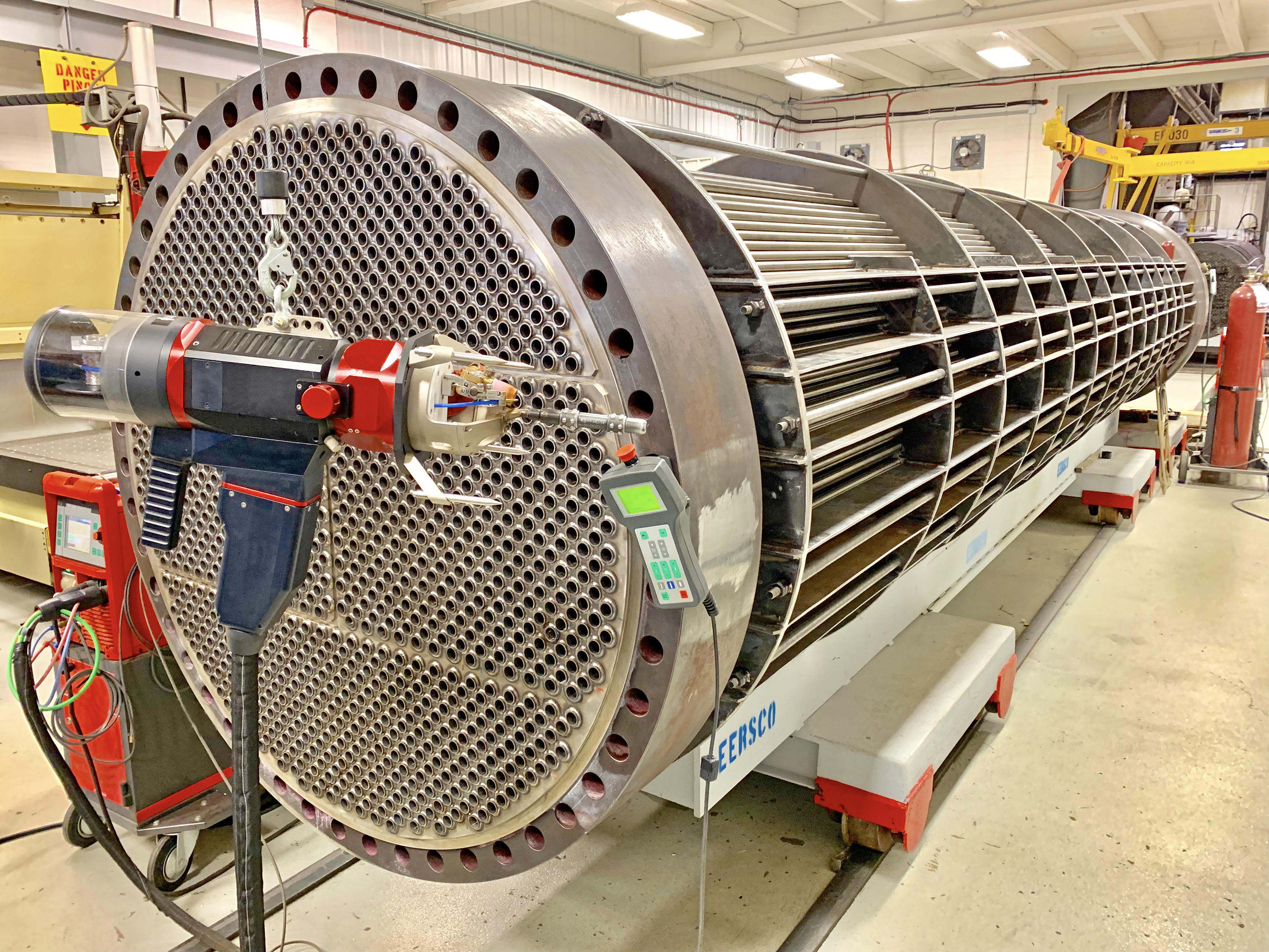
Plant real estate directly dictates equipment selection. You must evaluate both the permanent installation footprint and the temporary clearance required for maintenance. Shell and tube units require clearance equal to their own length to facilitate tube bundle extraction for cleaning and inspection. This often necessitates leaving large areas of the plant floor permanently empty or installing removable wall panels.
Compact plate designs require minimal maintenance clearance. Operators can open the frame and service the plates within the unit's existing footprint. When retrofitting older facilities or upgrading skid-mounted systems, replacing bulky tubular equipment with compact plate technology often frees up valuable floor space for additional production lines or auxiliary equipment.
Production demands rarely remain static. Evaluating how easily equipment adapts to increased capacity prevents premature obsolescence. Gasketed plate and frame units offer maximum scalability. Adding surface area only requires purchasing additional plates, inserting them into the pack, and tightening the frame bolts, provided the original frame was sized with extra capacity.
Conversely, shell and tube, brazed, and welded units have fixed surface areas. Increasing capacity requires installing a secondary unit in parallel, modifying the piping network, or replacing the entire system outright. Factoring future expansion into the initial selection process mitigates the risk of outgrowing your thermal infrastructure within the first few years of operation.
Industrial processing operates under strict regulatory frameworks. Verifying certifications based on your specific application is non-negotiable. Pressure vessels must adhere to ASME Section VIII standards in North America or the Pressure Equipment Directive (PED) in Europe to ensure mechanical safety under load. The oil and gas sector mandates API 660 for shell and tube units or API 662 for plate units to guarantee robust reliability in hazardous environments.
Sanitary applications, including food, beverage, and pharmaceuticals, require 3-A sanitary standards or FDA compliance. These standards dictate specific surface finish roughness, crevice-free geometries, and self-draining capabilities to prevent bacterial growth and cross-contamination. Failing to specify the correct regulatory standard results in failed inspections, voided insurance policies, and forced production shutdowns.
Selecting equipment based solely on the lowest initial purchase price often creates severe operational liabilities. Cheaper designs frequently compromise on material thickness, optimal channel geometry, or total surface area. This leads to reduced thermal efficiency, requiring more utility energy—such as steam or chilled water—to achieve the desired process temperature setpoints.
Furthermore, under-engineered units foul faster and require more frequent maintenance interventions. The labor required to repeatedly dismantle, clean, and reassemble a poorly specified unit quickly eclipses any initial savings. Prioritizing robust construction, appropriate sizing, and high-quality materials ensures long-term operational stability and predictable maintenance schedules.
Thermal efficiency and pressure drop exist in a permanent state of tension. Highly turbulent flow maximizes heat transfer, allowing for a smaller equipment footprint and less surface area. However, this turbulence generates significant fluid resistance, resulting in a high pressure drop across the unit.
Overcoming this pressure drop requires larger pumps and increased electrical consumption. You must analyze this trade-off carefully. Specifying a larger unit with wider channels reduces pressure drop and pumping requirements but increases the initial equipment size and material volume. Balancing these factors ensures optimal energy utilization across the entire process loop without overloading your existing pump infrastructure.
Maintenance protocols heavily influence equipment selection. You must evaluate the feasibility of Clean-in-Place (CIP) systems versus mechanical dismantling. Welded and brazed units rely entirely on CIP, requiring dedicated chemical tanks, circulation pumps, and specialized cleaning agents to dissolve internal scaling without opening the unit.
Units requiring mechanical cleaning demand significant labor hours. Hydro-blasting tube bundles at 10,000 psi or manually scrubbing hundreds of corrugated plates halts production for days. You must also account for the regular replacement of consumable components, such as elastomer gaskets, which degrade over time and require precise reinstallation to prevent leaks upon startup.
Even the most robust equipment eventually requires service. Evaluating a manufacturer's aftermarket support network is critical. When specifying Heat Transfer Equipment, you must confirm the availability of domestic spare parts and technical support.
Long lead times for replacement plates, custom tube bundles, or proprietary gaskets result in unacceptable facility downtime. Partnering with vendors who maintain extensive local inventory and offer rapid deployment of field service technicians mitigates the risk of extended production outages. Always request a recommended spare parts list during the initial procurement phase.
Fouling degrades thermal performance and increases pressure drop over time. Scaling occurs when dissolved minerals, like calcium carbonate, precipitate onto hot surfaces. Biological growth plagues open cooling water loops. Particulate deposition clogs narrow channels in untreated fluid streams, creating severe flow restrictions.
Mitigation requires proactive design choices. Oversizing the surface area provides a buffer against gradual efficiency loss, though excessive oversizing reduces fluid velocity and actually accelerates particulate settling. Increasing shear stress and fluid velocity helps scrub surfaces clean dynamically. Selecting appropriate plate corrugation patterns or specifying spiral designs specifically addresses heavy fouling environments before they cause operational failures.
Uneven flow across the heat transfer area creates localized hot spots, dead zones, or freezing risks. Maldistribution typically occurs when inlet nozzles are improperly sized, when manifold designs are flawed, or when fluid viscosity changes drastically during the thermal process, causing channeling.
Thermal stress presents a severe mechanical risk, particularly in shell and tube designs operating across wide temperature differentials. Rapid temperature fluctuations cause metals to expand and contract at different rates, leading to thermal fatigue, cracked welds, and tube rupture. Mitigating these risks requires proper internal baffling, the integration of expansion joints on the shell, and strictly controlled startup and shutdown procedures to prevent thermal shock.
Installing new equipment into existing piping networks carries significant logistical risks. Misaligned flanges, incompatible pipe diameters, or unexpected structural interferences extend installation timelines and halt production longer than anticipated.
Thorough integration planning requires precise 3D scanning of the installation site and detailed isometric piping diagrams. Pre-fabricating transition spools and structural supports before the shutdown window minimizes process interruption. Coordinating heavy lifting equipment, verifying floor loading capacities, and ensuring clear access routes prevents costly delays during the final installation phase.
Selecting the right thermal management equipment requires a rigorous balance of thermal physics, fluid constraints, and lifecycle maintenance capabilities. There is no universal solution; success depends entirely on identifying the most mathematically and operationally sound fit for your specific process parameters. Relying on accurate data rather than assumptions prevents costly operational failures.
To ensure a successful specification and installation, follow these immediate next steps:
Compile a comprehensive fluid profile, including exact viscosities, specific heat capacities, and particulate loads at operating temperatures.
Define your strict operational boundaries, documenting maximum allowable pressure drops, peak design temperatures, and required thermal duties.
Measure your physical installation space, accounting for both the permanent equipment footprint and the necessary clearance for maintenance access.
Consult with a specialized thermal engineer to run computational sizing models and compare the performance of at least two different equipment geometries.
Request a detailed maintenance schedule and spare parts availability guarantee from your shortlisted manufacturers before finalizing the purchase.
A: The terms are largely synonymous in industrial contexts. A heat exchanger refers specifically to the mechanical device transferring thermal energy between two distinct fluids without mixing them. Heat transfer equipment is a broader category that includes these devices alongside cooling towers, boilers, radiators, and thermal fluid heaters used throughout a facility.
A: Surface area is calculated using the total heat load, the overall heat transfer coefficient of the fluids, and the Log Mean Temperature Difference (LMTD). Because fluid properties change dynamically with temperature, engineers use specialized computational software to accurately model these variables and determine the exact square footage needed.
A: Pressure drop dictates the amount of pumping power required to push fluids through the unit. High pressure drop increases heat transfer efficiency by creating turbulence, but it requires larger pumps and consumes more electrical energy. Exceeding available pump capacity will reduce flow rates and cause the thermal process to fail.
A: Choose shell and tube designs for applications involving extreme pressures, temperatures exceeding 400°C, or significant phase changes like heavy steam condensation. They are also preferable when dealing with fluids containing large particulates that would quickly clog the narrow, corrugated channels of a plate and frame unit.
A: Fouling is caused by mineral scaling, biological growth, or particulate settling on transfer surfaces. Prevent it by maintaining high fluid velocities to create scrubbing shear stress, utilizing proper chemical water treatment, and selecting equipment designs specifically engineered to handle heavy debris, such as spiral or scraped surface units.
A: Capacity expansion depends entirely on the equipment type. Gasketed plate and frame units can easily be expanded by adding more plates to the existing frame. Shell and tube, brazed plate, and welded units have fixed surface areas and cannot be expanded without replacing the entire unit or adding another in parallel.


