

 注: 建议图片大小150px*50px
丨
English
注: 建议图片大小150px*50px Views: 0 Author: Site Editor Publish Time: 2026-08-22 Origin: Site
Thermal inefficiency directly drives operational cost overruns, spikes energy consumption, and creates severe process bottlenecks. When thermal transfer rates drop, facilities burn more fuel, consume more electricity, and struggle to hit production targets. The core problem lies in isolating the root causes of this performance degradation. Facility managers often struggle to distinguish between inherent design limitations, shifting process conditions, and cumulative maintenance failures. Pinpointing the exact failure mechanism is difficult but necessary. Operators need a systematic evaluation framework to assess equipment accurately. You must focus on baseline design parameters, precise material selection, and lifecycle degradation risks. Understanding these variables informs decisions regarding upgrades, routine maintenance, or new procurement. Whether you are troubleshooting a legacy unit or installing a new Heat Exchanger, evaluating efficiency requires looking beyond surface temperatures. You must analyze fluid dynamics, thermodynamic properties, and mechanical integrity to restore peak operational performance.
Design dictates baseline potential: Fluid properties (viscosity, density) and flow configurations establish the theoretical maximum efficiency of any heat exchanger.
Material selection requires trade-offs: High thermal conductivity must be balanced against corrosion resistance and lifecycle durability based on the specific process fluids.
Fouling is the primary operational risk: Scaling and particulate buildup act as thermal insulators, exponentially degrading heat transfer rates and increasing pressure drops.
Flow velocity is a delicate balance: Optimal flow rates maximize heat transfer and minimize fouling, but excessive velocity causes erosion and inflates pumping costs.
Proactive monitoring drives ROI: Continuous assessment of the overall heat transfer coefficient (U-value) and approach temperatures is critical for determining when to clean, retrofit, or replace a unit.
Understanding efficiency starts with defining actual heat transfer against the maximum possible heat transfer. Thermal efficiency in practice relies heavily on the Overall Heat Transfer Coefficient, commonly known as the U-value. This metric represents how effectively heat transfers through a conductive barrier between two fluids. A higher U-value indicates superior performance. However, this value is never static. It fluctuates based on flow rates, fluid properties, and internal cleanliness. Establishing a baseline U-value during initial commissioning gives you a definitive benchmark. You can then measure future performance degradation against this original standard.
To properly establish these baseline metrics, site engineers should follow a strict documentation process during commissioning:
Record the initial commissioning U-value under clean conditions to serve as the absolute performance ceiling.
Document the baseline pressure drop across both the hot and cold fluid circuits at standard operating flow rates.
Log the exact fluid flow rates and inlet/outlet temperatures during peak production to verify design specifications.
Establish the baseline approach temperature to monitor future thermal degradation accurately.
Maximizing thermal transfer only succeeds if it avoids unacceptable pressure drops. The pressure drop variable is a strict constraint in any thermal system. Forcing fluids through tight corrugated channels increases turbulence and heat transfer. Unfortunately, it also creates significant hydraulic resistance. Pumps must work harder to overcome this resistance. If the pressure drop exceeds design limits, pumping energy costs will rapidly erase any savings gained from improved thermal efficiency. You must balance thermal gains with hydraulic limitations.
Evaluating a Heat Exchanger System requires strict alignment between capital expenditures (CAPEX) and operating expenses (OPEX). High-efficiency designs often carry a larger initial capital requirement. They utilize complex geometries and premium alloys. However, these units typically consume less energy and require less maintenance downtime over their lifecycle. A robust evaluation framework weighs this initial capital cost against long-term operating expenses. Cheaper upfront units often fail faster, foul quicker, and demand excessive pumping power.
Modern efficiency evaluations must also account for aggressive sustainability goals. Industrial facilities face increasing pressure to lower their carbon footprint. Waste heat recovery is a primary method for achieving decarbonization. You must measure how effectively your equipment captures waste heat from exhaust streams or hot effluents. Reusing this thermal energy reduces the demand on primary boilers and chillers. A highly efficient unit directly translates to lower fuel consumption and reduced greenhouse gas emissions.
The inherent physical properties of your process fluids dictate baseline efficiency. Density and viscosity play massive roles in system performance. High-viscosity fluids resist flow naturally. They create thick boundary layers along the heat transfer surfaces. This elevates the pressure drop and inhibits thermal exchange. Engineers must utilize specific internal geometries, like wide-gap plates or specialized baffles, to maintain turbulent flow when handling viscous media. Without these design adaptations, viscous fluids will severely throttle system efficiency.
Specific heat capacity and thermal conductivity also define equipment requirements. Specific heat capacity determines how much thermal energy a fluid can absorb or release. Thermal conductivity measures how fast that heat moves through the fluid itself. Fluids with low thermal conductivity require significantly more surface area to achieve the desired temperature setpoints. Water transfers heat exceptionally well. Oils and hydrocarbon mixtures do not. You must size the surface area precisely based on these inherent fluid capabilities.
Phase change dynamics drastically alter efficiency calculations. Applications involving phase changes, such as condensers or evaporators, deal with latent heat. Sensible heating or cooling only changes fluid temperature without changing its state. Latent heat transfer absorbs or releases massive amounts of energy at a constant temperature. This process is generally highly efficient. However, it requires specialized vapor distribution spaces and precise condensate drainage to maintain optimal surface area contact. If condensate floods the tubes, the available surface area shrinks, and performance drops immediately.
Optimizing flow velocity requires precise engineering. Velocities that are too low create sluggish movement. This promotes rapid fouling, scaling, and poor heat transfer. Particulates settle easily when fluid moves slowly. Conversely, velocities that are too high cause severe mechanical erosion. High speeds strip away protective oxide layers on metal surfaces. They also inflate the pressure drop exponentially. Finding the optimal flow rate maximizes heat transfer while mitigating both fouling and erosion risks.
Inducing turbulent flow is essential for maximizing thermal efficiency. Laminar flow moves in smooth, parallel layers. It creates a stagnant thermal boundary layer against the metal surface. This boundary layer acts as an insulator. Turbulent flow disrupts this layer. It mixes the fluid aggressively, bringing fresh fluid into direct contact with the heat transfer surface. Internal corrugations and specific tube layouts are designed specifically to break laminar flow and force beneficial turbulence. Engineers calculate the Reynolds number to ensure the flow regime remains turbulent under normal operating conditions.
Counter-flow is generally the most efficient fluid configuration available. In this setup, the hot and cold fluids enter from opposite ends and flow past each other in opposite directions. This arrangement maintains a consistent temperature gradient across the entire length of the unit. It allows for the highest possible log mean temperature difference (LMTD). A higher LMTD means a smaller required surface area, leading to a more compact and cost-effective design.
Cross-flow and parallel flow serve specific alternative use cases. Parallel flow involves both fluids entering the same end and traveling in the same direction. It is less efficient because the temperature gradient collapses quickly as the fluids approach equilibrium. However, parallel flow is useful when you need to limit the maximum wall temperature to prevent fluid degradation. Cross-flow directs fluids perpendicular to each other. It is commonly used in air-cooled units where gas flows over liquid-filled tubes. Both configurations carry inherent thermal efficiency penalties compared to counter-flow.
Thermal Flow Configuration Comparisons
Configuration Type | Thermal Efficiency Potential | Primary Application | Limitations |
|---|---|---|---|
Counter-Flow | Highest | Liquid-to-liquid thermal transfer, close approach temperatures. | Requires complex piping arrangements in tight spaces. |
Parallel Flow | Lowest | Handling heat-sensitive fluids to prevent thermal degradation. | Temperature gradient collapses quickly, requiring more surface area. |
Cross-Flow | Moderate | Air-cooled condensers, HVAC coils, gas-to-liquid systems. | Uneven temperature distribution across the tube bundle. |
Matching the physical architecture to the application is non-negotiable. Shell and tube designs offer massive pressure and temperature tolerances. They are robust but require significant floor space. Plate and frame designs provide exceptional thermal efficiency in a compact footprint. They excel with close approach temperatures but struggle with extreme pressures. Finned-tube designs are ideal for gas-to-liquid applications where the gas side requires extra surface area to compensate for poor thermal conductivity.
Surface area optimization relies heavily on internal enhancements. Engineers use corrugated plates, baffled shells, and finned tubes to increase the effective surface area within a confined space. These enhancements do more than just add metal. They actively induce beneficial turbulence and direct fluid flow to eliminate dead zones. Optimizing these internal geometries ensures that every square inch of the unit contributes actively to the thermal transfer process.
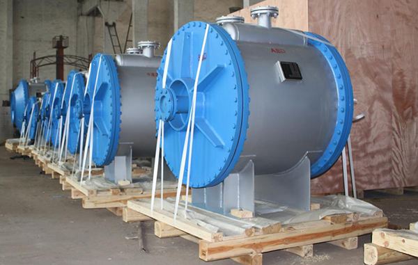
Material selection establishes the baseline thermal conductivity of the physical barrier. Standard materials vary wildly in their conductive capabilities. Carbon steel is cheap and moderately conductive but highly susceptible to rust. Stainless steel resists corrosion well but suffers from relatively poor thermal conductivity. Copper alloys transfer heat brilliantly but degrade quickly in aggressive chemical environments. Titanium offers extreme corrosion resistance for saltwater applications but carries a premium cost and lower conductivity than copper.
Engineers constantly navigate the durability trade-off. Highly conductive materials often fail when exposed to aggressive chemicals or high-velocity particulates. You cannot prioritize thermal efficiency if the unit corrodes and leaks within six months. Often, you must select a material that slightly lowers theoretical efficiency to prevent rapid mechanical failure. A thicker, less conductive alloy ensures long-term operational stability. You compensate for the lost conductivity by adding more total surface area to the design.
Common Metallurgical Properties for Thermal Applications
Material | Baseline Conductivity | Corrosion Resistance | Typical Field Application |
|---|---|---|---|
Carbon Steel | Moderate | Low | Standard utility water, non-corrosive oils. |
316 Stainless Steel | Low | High | Food processing, mild chemical processing. |
Copper Alloys | Very High | Moderate | HVAC chillers, clean water systems. |
Titanium | Low | Extreme | Seawater cooling, highly aggressive acids. |
Chemical aggression and temperature extremes dictate metallurgical requirements. Selecting the wrong material leads to accelerated degradation. Acids, chlorides, and reactive hydrocarbons will rapidly consume incompatible metals. When dealing with corrosive fluids, designers must specify thicker tube walls to allow for a calculated corrosion allowance over time. Unfortunately, thicker walls increase thermal resistance. You must accurately match the metallurgy to the fluid chemistry to avoid over-engineering the wall thickness and sacrificing thermal performance.
Fouling remains the primary threat to sustained thermal efficiency. You must categorize the specific threat to fight it effectively. Particulate fouling occurs when sand, silt, or rust settles out of the fluid onto the surfaces. Crystallization, or scaling, happens when dissolved minerals like calcium carbonate precipitate out of solution due to temperature changes. Biological fouling involves algae, bacteria, or mussels growing inside warm water channels. Chemical reaction fouling occurs when the process fluid itself degrades and bakes onto the hot surfaces.
All forms of fouling create a severe insulator effect. The physics are straightforward. Even microscopic layers of scale or biofilm possess extremely low thermal conductivity. For context, calcium carbonate scale has a thermal conductivity roughly two percent that of carbon steel. It creates a physical thermal barrier between the fluid and the metal plate. This barrier drastically reduces the heat transfer rate. As the fouling layer thickens, the U-value plummets. The system must then consume more heating or cooling energy to achieve the exact same process temperatures.
Fouling does not just block heat; it physically restricts flow. As scale or debris accumulates, it reduces the cross-sectional flow area inside the channels or tubes. This flow restriction acts like a clogged artery. To maintain the required volumetric flow rates, system pumps must work significantly harder. They consume more electrical energy to push fluid through the narrowed passages. This pressure drop penalty often costs facilities more in electricity than the lost thermal efficiency costs in fuel.
Uneven fouling leads directly to fluid maldistribution. When certain channels clog faster than others, the fluid takes the path of least resistance. It channels heavily through the remaining open passages. This means large sections of the heat transfer surface are bypassed entirely. Maldistribution destroys the carefully engineered temperature gradients within the unit. It causes localized hot spots, accelerates further fouling in the slow-flow areas, and cripples overall system performance.
Mechanical degradation actively destroys system integrity. Localized corrosion, such as pitting or crevice corrosion, attacks specific weak points in the metal. Pitting creates microscopic holes that penetrate deep into the tube walls. Crevice corrosion thrives under gaskets or beneath heavy scale deposits. Over time, these localized attacks compromise structural integrity. They weaken the pressure boundaries and inevitably lead to catastrophic mechanical failures if left unmonitored.
Efficiency loss via contamination is a severe operational hazard. Internal leaks allow the hot and cold fluid streams to mix. This instantly destroys process efficiency. More importantly, it creates severe safety and compliance risks. If a toxic chemical stream leaks into a cooling water loop, it triggers environmental violations and forces immediate plant shutdowns. Cross-contamination ruins product batches and demands emergency maintenance interventions.
Peripheral systems heavily influence overall thermal efficiency. Inefficiencies in connected equipment compound overall thermal losses. For example, in steam-driven systems, boiler blowdown and deaerator losses waste significant amounts of heat. If the steam traps fail or the condensate return system leaks, the primary unit cannot operate efficiently. You must evaluate the entire thermal loop, not just the isolated exchanger, to capture true operational efficiency.
Flow blockages represent sudden and severe efficiency killers. Macro-fouling occurs when large debris enters the system. Items like plastic wrappers, broken pump impellers, or large organic matter can physically obstruct flow paths. These blockages instantly spike the pressure drop and starve the unit of necessary fluid. Installing proper upstream filtration and strainers is mandatory to protect the internal channels from macro-fouling events.
Ambient heat loss silently drains system efficiency. Inadequate external insulation allows radiant and convective heat to escape into the surrounding environment. If a unit operates at high temperatures, bare metal surfaces will bleed thermal energy constantly. This lowers the net efficiency of the system. Proper lagging and weather-proof insulation jackets are required to keep the thermal energy contained within the process fluids where it belongs.
Monitoring the U-value is the most definitive way to track performance. You must calculate the overall heat transfer coefficient continuously over time. By comparing the current U-value against the clean baseline U-value, you identify exact degradation trends. A steadily declining U-value confirms that fouling is accumulating. Tracking this metric removes guesswork and allows engineers to schedule maintenance based on actual data rather than arbitrary calendar dates.
Approach temperature tracking serves as an excellent early warning system. The approach temperature is the difference between the exiting hot fluid and the entering cold fluid. In an efficient system, this temperature gap is tight. As fouling builds and efficiency drops, the approach temperature widens. Operators can easily monitor these temperature differentials on a daily shift basis to spot sudden performance drops before they trigger critical process alarms.
Automated monitoring systems transform maintenance strategies. Modern facilities rely on IoT sensors and continuous data logging. These systems track inlet and outlet temperatures, flow rates, and differential pressures in real-time. They provide automated alerts for pressure drop spikes or thermal efficiency degradation. IoT integration allows for predictive maintenance, ensuring you only take the unit offline when the data proves it is absolutely necessary.
Selecting the right cleaning modality impacts downtime and effectiveness. Mechanical cleaning, such as high-pressure hydro-blasting, physically removes hard scale and baked-on deposits. It is highly effective but requires complete unit disassembly. Clean-in-Place (CIP) utilizes heated chemical solvents circulated through the unit. CIP requires less downtime and avoids disassembly, but it may struggle to remove severe, hardened blockages. You must match the cleaning method to the specific fouling type.
Determining maintenance frequency is a financial calculation. You must calculate the optimal cleaning schedule that balances the cost of downtime against the cost of lost thermal efficiency. Cleaning too often wastes labor hours and production time. Waiting too long inflates energy bills and risks permanent equipment damage. Data-driven monitoring allows you to pinpoint the exact moment when the cost of lost efficiency exceeds the cost of a cleaning intervention.
Knowing when to retrofit saves significant capital. Scenarios often arise where upgrading specific components is highly cost-effective. Swapping standard plates for high-efficiency corrugated plates can instantly boost thermal transfer. Adding twisted-tape tube inserts can induce turbulence in sluggish shell and tube units. Retrofitting allows you to leverage the existing footprint and piping infrastructure while upgrading the internal thermodynamic capabilities.
Knowing when to replace prevents catastrophic failures. Indicators that a unit has reached the end of its lifecycle include chronic leaks and severe metallurgical fatigue. If the shell is thinning beyond safe pressure tolerances, replacement is mandatory. If your facility has scaled up production, a legacy unit may simply be too small. A fundamental mismatch with modern process demands requires a complete replacement to avoid throttling plant output.
Retrofit vs Replacement Decision Matrix
Condition | Retrofit Indicator | Replacement Indicator |
|---|---|---|
Thermal Performance | Minor U-value drop; can be fixed with new high-efficiency plates. | Severe, unrecoverable U-value drop despite chemical cleaning. |
Mechanical Integrity | Localized gasket leaks or minor tube sheet wear. | Chronic internal leaks, metallurgical fatigue, or severe pitting. |
Process Demands | Slight flow increase; can add plates to existing frame. | Fundamental mismatch with newly scaled-up process demands. |
Maintenance Frequency | Fouling can be managed with tube inserts or better coatings. | Unit requires constant disassembly, causing unacceptable downtime. |
Conduct a baseline thermal audit of your current operating units to identify immediate efficiency gaps.
Calculate current U-values and compare them directly against the original manufacturer design specifications.
Install differential pressure sensors across all fluid inlets and outlets to track flow restriction in real-time.
Consult with thermal engineering specialists to identify targeted retrofit opportunities for legacy equipment.
A: Fouling is the most common cause. The accumulation of scale, particulates, or biological growth on the heat transfer surfaces acts as a powerful thermal insulator. This buildup blocks heat transfer and simultaneously restricts fluid flow, causing severe pressure drops.
A: Cleaning frequency depends entirely on the process fluids and operational data. Instead of using a fixed calendar schedule, monitor the U-value and pressure drop. Clean the unit when the cost of lost energy and pumping power exceeds the cost of maintenance downtime.
A: A rising pressure drop indicates that the internal flow channels are becoming restricted. This is typically caused by severe fouling, scaling, or macro-debris blocking the passages. It forces pumps to work harder and signals that cleaning is urgently required.
A: Yes. Different fluids have unique viscosities, densities, and thermal conductivities. If you introduce a more viscous fluid or one with lower thermal conductivity, the existing surface area may no longer be sufficient to meet your temperature setpoints.
A: The U-value is calculated using the total heat transfer rate, the available surface area, and the log mean temperature difference (LMTD). By continuously logging inlet and outlet temperatures alongside flow rates, automated systems can calculate and track the U-value in real-time.
A: Counter-flow maintains a consistent temperature gradient across the entire length of the unit. It prevents the fluid temperatures from reaching equilibrium too quickly. This maximizes the log mean temperature difference, allowing for greater total heat transfer in a smaller footprint.


