

 注: 建议图片大小150px*50px

丨
English
注: 建议图片大小150px*50px Views: 0 Author: Site Editor Publish Time: 2026-11-11 Origin: Site
When designing a high-pressure piping network, every component must be meticulously selected to ensure operational safety, hydraulic efficiency, and structural longevity. Among these critical elements, the Stainless Steel Elbow plays a fundamental role in safely redirecting the flow of highly pressurized fluids or volatile gases. However, engineers frequently encounter a complex design dilemma regarding which curvature profile is best suited for extreme applications. Choosing an incorrect bend can trigger dangerous pressure drops, accelerate internal pipe erosion, or even precipitate catastrophic system failure under peak stress. In this comprehensive guide, we will explore the objective technical differences between gradual and compact sweeping bends, examine the structural necessity of welded joints, and explain how global manufacturing codes dictate the safest choices for your pipelines.
Gradual Sweeps are Generally Preferred: For high-pressure systems, a curvature measuring 1.5 times the diameter offers smoother fluid dynamics, significantly less turbulence, and lower frictional resistance compared to tighter alternatives.
Compact Bends have Niche Uses: The tighter profile is typically reserved for low-pressure systems or extremely tight spatial constraints, as the sharp turn creates higher flow resistance and dangerous stress concentrations.
Connection Integrity Matters: A continuous welded joint remains the undisputed industry standard for demanding applications, providing superior structural integrity, excellent fatigue resistance, and a permanent leak-proof seal.
Compliance is Non-Negotiable: High-pressure pipe fittings must strictly adhere to recognized dimensional standards to guarantee reliable performance under extreme operational stress.
Wall Thickness is Crucial: The bend profile alone does not dictate overall capacity. The pipe schedule and material grade must precisely match the internal demands of the network.
To make an informed engineering decision, it is essential to grasp how pipe elbow curvatures are measured and categorized on the fabrication floor. The radius refers to the physical sweep of the fitting, dictating exactly how abruptly the internal flow changes trajectory. In industrial piping, this geometry is universally measured relative to the nominal pipe diameter.
Specifically, a Long Radius elbow features a centerline curvature equal to 1.5 times the nominal pipe diameter. For instance, if a field technician is routing a 4-inch line through a refinery, this specific fitting would require a 6-inch centerline sweep. Because of its highly balanced flow characteristics and structural reliability, this gradual sweep serves as the default choice in heavy industrial networks.
In contrast, a Short Radius elbow has a centerline dimension equal to exactly 1.0 times the nominal diameter. Using that same 4-inch example, the compact counterpart creates a tight 4-inch turn. While highly advantageous when navigating compact machinery or densely packed facility skids, this abrupt directional shift significantly alters fluid dynamics and internal pressure distribution.
Before directly comparing specific profiles, we must examine what physically transpires inside a pipeline when highly pressurized media is forced to rapidly change direction. A piping network is not a static entity. Rather, it is a highly dynamic environment where kinetic energy, outward force, and metallurgical resistance constantly battle.
Whenever a pressurized liquid or gas navigates a corner, it naturally encounters physical resistance against the inner wall. This directional shift inevitably causes a drop in head pressure. The sharper the turn, the higher the equivalent length of straight pipe it represents in hydraulic calculations. Consequently, downstream pumps and compressors are forced to work significantly harder, leading to increased energy expenditure and premature mechanical wear.
Furthermore, smooth laminar flow is the ideal state for pipeline longevity. Sharp turns aggressively disrupt this orderly movement, forcing the fluid to separate from the inner curve and crash into the outer wall. In liquid systems, this severe turbulence can trigger cavitation. This destructive phenomenon occurs when vapor bubbles rapidly form and violently collapse. The resulting micro-vibrations send shockwaves through the metal, ultimately causing severe pitting and mechanical fatigue.
High-velocity streams also exert immense shear stress against the extrados, or outer curve, of the fitting. This constant physical bombardment becomes particularly destructive if the fluid contains abrasive particulates like sand in oil extraction or catalysts in chemical slurries. Over years of continuous operation, this abrasive action gradually thins the metal wall, drastically increasing the risk of a dangerous blowout.
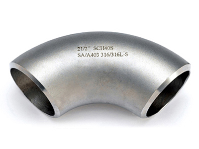
When evaluating which profile suits extreme environments, empirical data and fluid dynamics strongly favor one specific option. The extended curve of a gradual fitting minimizes internal flow separation and greatly reduces frictional resistance. By allowing the highly pressurized fluid to change direction more gently, the internal stream remains relatively stable. This critical reduction in turbulence translates directly to lower localized stress on the outer wall. Consequently, the fitting experiences far less mechanical wear, making the gradual configuration significantly safer and more efficient for demanding transmission lines.
Applying a compact turn in a high-pressure scenario introduces substantial operational risks. The abrupt geometry forces a violent change in fluid direction, causing a pressure drop that can be up to 30 percent higher than its gradual counterpart. In addition, the tighter bend radius means the metal on the outer curve is stretched thinner during manufacturing, creating higher inherent stress concentrations. When subjected to extreme outward forces, these localized stress points become highly susceptible to micro-cracking or outright rupture.
To provide a clear engineering perspective, below is a core technical comparison detailing how these two profiles perform under stress:
Performance Metric | Long Radius Sweep | Short Radius Sweep |
|---|---|---|
Frictional Resistance | Low. Maintains optimal fluid momentum. | High. Creates significant head pressure loss. |
Turbulence & Cavitation Risk | Minimal. Promotes stable laminar flow. | Severe. Prone to flow separation and pitting. |
Outer Wall Stress Concentration | Evenly distributed across the extended curve. | Highly localized. Increases risk of metal fatigue. |
Best Engineering Application | High-pressure transmission, chemical processing. | Low-pressure systems, tight machinery skids. |
The gradual design remains the undisputed gold standard for high-pressure systems. Tighter bends should only be utilized when unavoidable spatial constraints make standard installation physically impossible. Even in those rare instances, piping engineers must perform rigorous stress analyses and typically specify a heavier pipe schedule to compensate for the severe flow dynamics.
The physical curvature is only one piece of the complex engineering puzzle. How the fitting permanently integrates into the adjacent pipeline is equally vital for safely containing extreme forces. A system is ultimately only as strong as its weakest joint.
A Butt Weld connection involves joining the elbow and the pipe end-to-end. Field technicians precisely bevel the ends of both components to create a V-shaped groove. This groove is then filled with molten filler metal, fusing the two pieces into a single continuous structure.
When compared to threaded or socket weld alternatives, end-to-end welding offers unparalleled reliability. Threaded joints rely on physical interlocking and sealing compounds, making them inherently prone to leaking under frequent thermal cycling or extreme outward force. Socket welds create tiny internal crevices that trap corrosive materials and induce localized turbulence. In stark contrast, a properly executed end-to-end weld eliminates these gaps entirely. It provides a seamless transition with the highest possible tensile strength, ensuring the internal surface remains perfectly smooth to further reduce flow resistance.
Looking at the broader industrial landscape, the engineering approach to high-pressure piping systems is rapidly evolving. Modern facilities are increasingly pushing the boundaries of operational pressure and temperature to maximize production efficiency. This is particularly evident in deep-water offshore drilling, advanced chemical synthesis, and the emerging hydrogen transport sector.
Recent industry shifts highlight a massive reliance on computational fluid dynamics simulation during the design phase. Engineers no longer rely solely on static charts. They actively simulate how volatile fluids impact the extrados of an elbow at extreme velocities before a single pipe is laid. This data-driven approach has overwhelmingly reinforced the preference for gradual sweeps in high-stress environments. Furthermore, with the rising global focus on environmental safety and zero-emission targets, regulatory bodies are enforcing stricter compliance audits. Consequently, procurement teams are moving away from commoditized fittings. They now prioritize fully traceable, high-grade stainless steel components that offer documented fatigue resistance over decades of continuous operation.
Industrial buyers, procurement managers, and field engineers must rely on standardized manufacturing protocols to ensure operational safety and legal compliance. In the realm of factory-made wrought fittings, adherence to recognized codes is absolutely non-negotiable.
ASME B16.9 is an internationally recognized standard established by the American Society of Mechanical Engineers. It explicitly dictates the overall dimensions, strict tolerances, testing requirements, and marking protocols for wrought buttwelding fittings across various sizes ranging from 1/2 inch up to 48 inches.
By strictly adhering to these guidelines, premium manufacturers ensure that every single fitting meets exact dimensional tolerances. This microscopic precision is critical for high-pressure systems. Even a single millimeter of misalignment during the welding process can create a dangerous stress riser in the pipeline, eventually leading to fatigue failure. Fittings manufactured to these specifications are explicitly designed to match the pressure and temperature ratings of seamless pipes made from the equivalent material and wall thickness. This guarantees system-wide consistency.
To make a confident purchasing decision, design teams must evaluate the holistic properties of the component. Extreme internal forces intrinsically require thicker walls for safe containment. Pipe schedules such as Schedule 80, Schedule 160, or Double Extra Strong are standard for heavy-duty lines. The sweep profile will not prevent a blowout if the chosen wall thickness is simply too thin to withstand the system peak operating pressure.
The specific alloy determines both physical yield strength and chemical corrosion resistance. While standard 304 or 304L is suitable for benign high-pressure water networks, 316 or 316L contains added molybdenum. This critical addition offers superior tensile strength and excellent resistance to pitting in harsh chemical processing or marine environments. Premium suppliers provide these fittings in standard 45-degree, 90-degree, and 180-degree angles, available in both seamless and welded construction to match exact project specifications.
Selecting the correct geometry and specification is critical across multiple heavy industries where pipeline integrity is a matter of human safety and environmental protection.
Oil and Gas Refineries: These massive facilities process highly volatile hydrocarbons under extreme conditions. A smooth flow path is essential to prevent dangerous pressure buildup and mitigate the abrasive degradation caused by sand and sulfur compounds.
Chemical Processing Plants: Handling aggressive fluids at elevated temperatures requires the robust combination of thick-walled gradual sweeps and high-grade alloys to combat severe internal erosion.
Power Generation: Both nuclear and thermal power plants rely heavily on high-pressure steam lines to drive massive turbines. The minimal turbulence of a gradual radius prevents dangerous steam cavitation and costly efficiency losses.
Hydraulic Systems: Heavy industrial machinery and offshore equipment depend on robust directional fluid control. Seamless welded joints ensure leak-free operation under constant punishing pressure cycles that frequently exceed 10,000 PSI.
While compact bends certainly have their place in space-restricted or low-pressure environments, the gradual sweep remains the undisputed champion for high-pressure applications. Its extended curve preserves fluid momentum, minimizes dangerous internal turbulence, and significantly reduces mechanical stress on the pipeline infrastructure. To guarantee a safe, durable, and highly efficient piping network, engineers should always pair these gradual fittings with seamless end-to-end welded joints and ensure strict compliance with global manufacturing standards.
Ultimately, consulting with trusted manufacturers to source the exact material grade, schedule, and bend profile required for your specific project is the most reliable path to long-term operational success. If you are upgrading a facility or designing a new high-pressure network, explore the premium selection of compliant, heavy-duty pipe fittings at Graceland to ensure your system operates safely under the most extreme conditions.
Yes, but it is highly discouraged and not recommended unless spatial constraints absolutely require it. If you are forced to use a tighter bend in a demanding system, engineers must mathematically compensate by significantly increasing the pipe schedule and rigorously calculating the expected pressure drop and stress concentrations to prevent premature failure.
The term indicates that the centerline radius of the fitting is exactly 1.5 times the nominal diameter of the connecting pipe. For example, a 4-inch nominal pipe will require a fitting with a 6-inch centerline sweep. This specific geometry creates a gradual bend that is ideal for maintaining fluid momentum and reducing internal friction.
While socket weld connections can handle moderate to high pressures in much smaller pipe diameters, end-to-end welded joints are universally recognized by piping engineers as the strongest and most reliable connection method for high-pressure and high-temperature systems across all pipe sizes.
Absolutely. Recognized industry standards provide comprehensive dimensional, tolerance, and testing protocols for both gradual and compact factory-made wrought buttwelding fittings. This ensures strict manufacturing consistency and interoperability regardless of the specific geometry chosen for your project.
Different metal alloys possess vastly different yield and tensile strengths. For instance, a 316L alloy offers excellent structural strength and superior corrosion resistance compared to standard 304. This makes 316L a significantly better and safer choice for networks handling aggressive chemicals, marine offshore applications, or extreme temperature fluctuations.
Calculating the pressure drop involves determining the equivalent length of straight pipe that the bend represents. Engineers use the Darcy-Weisbach equation combined with a specific resistance coefficient based on the bend radius. A gradual sweep will have a significantly lower resistance coefficient than a compact bend, resulting in a much smaller calculated pressure drop.
The schedule number directly refers to the wall thickness of the fitting. Schedule 160 has a significantly thicker metal wall than Schedule 80, allowing it to contain much higher internal pressure without rupturing. When dealing with extreme hydraulic forces, upgrading from Schedule 80 to Schedule 160 or even Double Extra Strong is a standard engineering practice to ensure structural safety.


